5 Minute Telescope Tripod/Mount Setup
This article describes several mods to a telescope tripod (and equatorial mount) so it can be rolled on pavement, positioned, and aligned quickly. This whole idea may be well-known to amateur astronomers everywhere but I don't know since I don't know any other amateur astronomers. The process of positioning & aligning can be completed in about 5 minutes from roll-out and I'm ready to move on to the activities of the night's observations.
This particular scope mount is an iOptron CEM25P on an iOptron tripod. The mount has a built-in iOptron "AccuAlign" Polar Scope. The stock tripod is marginal, but I live in a covenant controlled community and I am not allowed an observatory or even a permanent pier, so I had to make due. Since the scope has to be set-up and taken down each night, I desired a way to quickly move the tripod from the garage to the driveway and align it in as short a time as possible.
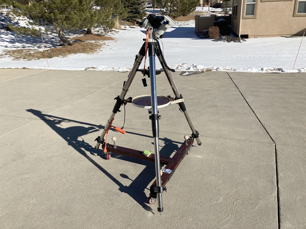
Figure 1. iOptron tripod, and mount with stabilizing cross-bracing.
The first thing I did was to make the tripod more stable by installing two cross-braces between the tripod legs (visible in Figure 1). The upper cross-brace "rigidizes" the legs, and provides for a small table on which I can set lens caps, and other small parts where they are conveniently located. (A lip on the table prevents things from falling off the table.) The lower cross-brace was designed in the shape of a "T" to not only "rigidize" the lower legs of the tripod but also to provide for a mechanism to transport the tripod from the garage to the driveway where most of my observing takes place. (Of course, the cross-braces prevent the tripod from easily being collapsed, but the cross-braces are removable should the need arise.)
The cross-braces do quite well to make the tripod legs more "rigid" and the tripod less prone to vibration. I will not describe their design here as this article is not about the the cross-braces, except to say that they are held to the tripod legs using "wrap-around" clamps like these, (sometimes called an "O-clamp", "Stage Light clamp", or "Truss Clamp"), available at Amazon.com and come in different sizes for different diameter legs:

Figure 2. Example of the "wrap-around" clamps used to attach the cross-braces to the telescope tripod.
The lower cross-brace was designed as a "T" so the entire tripod, even with the telescope and counterweight installed, could be transported to the driveway using a 2-wheel hand truck as seen here:
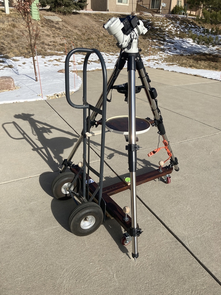
Figure 3. The tripod can also be moved using a two-wheel hand truck.
The lower cross-brace sits above the lip of the hand truck (with some boards taking up the gap from the lip to the underside of the cross-brace) while a "hook" (Figure 4) firmly connects the top shelf of the tripod to the hand truck. With the hook in-place, tilting back the hand truck literally pulls the tripod with it so the operator need only steady the tripod on the hand truck so it is not allowed to fall over. The tripod is top-heavy one must be careful so the tripod does not fall off the hand truck!

Figure 4. A simple "hook" holds the tripod shelf firmly to the hand truck while the hand truck is tilted back for transport.
Though the hand truck works quite well, it did not solve my problem of positioning the tripod so when it is lowered off the hand-truck it is already close to the desired alignment to the north. In this case, when the tripod is lowered to the pavement and the hand truck disconnected, I had no idea if the tripod was even close to roughly aligned to the north, and no way to resolve the dilemma. Adjusting azimuth of the legs of a heavy tripod, is quite a slow, tedious process requiring lifting two legs to simultaneously to shift them laterally a bit, then check the polar scope and shift them again until Polaris is seen in the polar scope! Worse, initial orientation of the tripod had to wait till dusk when Polaris would become visible.
I really needed another process. A complete method providing for:
- An easy way to quickly move the tripod (with or without the scope already attached) from the garage to the location desired on the driveway. This was partially met with the hand-truck, but was not ideal due to #2.
- A way to quickly position the tripod legs so the mount was already nearly pointing to true north once. The more precise the tripod can be initially positioned to line up the mount with the true north the better. That way, only a fine alignment is needed each time the scope is set up.
- A way to then quickly level the tripod so the mount is level no matter the slight slope of the driveway. Boards and wedges under each tripod foot was out of the question as that would be too time consuming. The iOptron mount (as do most mounts) has a tiny built-in bubble level but it is hard to see, especially at dusk. A more accessible level was needed.
- Once the tripod is positioned and leveled, a way to quickly finely adjust the azimuth and altitude of the RA axis of the mount to precisely align with the Earth's polar axis. (Of course, this mount already has built-in a Polar Scope but I'm talking about speeding up the alignment process while looking through the Polar Scope - which is awkward enough!)
Ultimately:
#1 was accomplished by the use of wheels.
#2 was accomplished by the use of a magnetic compass.
#3 was accomplished by "jack screws" and a large bubble level.
#4 was accomplished by improving the miserable latitude adjusting knob on the iOptron mount and replacing the short azimuth adjusting bolts on the mount with longer ones so they could be more easily located and gripped by feel alone while looking through the built-in Polar Scope.
Summary of the modifications
#1. The wheels. I chose 3" heavy-duty casters since the tripod, telescope and counterweight would be held up by the wheels sometimes for extended periods and I did not want the wheels developing flat-spots. This, of course, means the wheels are not shock-absorbing, but I thought I could live with that. Here's a photo of one of the caster wheels installed. They are simply lag-bolted to the bottom of the T-cross-brace. They are positioned as far out-board as possible, closest to the tripod legs for stability and since the jackscrews could not be placed close to the tripod legs:

Figure 5. One of the 3 wheels installed under the lower tripod cross-brace.
With the wheels installed, (and the jackscrews raised), the feet of the tripod no longer touch the ground. The tripod always rests on the wheels so the tripod can be rolled about at will.
Once rolled to the desired location and oriented, the jackscrews are used to raise the tripod off the wheels. But first, the process of orientation:
#2. The Compass.
As alluded to above, a significant need was to already have the Right Ascension axis aligned very close to true north as soon as the tripod is positioned. I needed a way to approximately find the orientation to true north during the daytime, i.e., without the ability to see the North Star. That way, I could position the tripod well before sunset, and know that all I needed to do was perform the fine alignment.
To do this, it occurred to me to use an ordinary magnetic compass. I had a Boy Scout magnetic compass for a long time, which has a bezel which can be twisted to position an arrow to account for the magnetic declination offset of a location. I aligned the compass to the tripod by first performing a full alignment of the telescope and then adjusting the compass' bezel to the magnetic declination of my location.

Figure 6. Boy Scout compass attached to the tripod.
After that, to align the tripod to the North-South position simply means rolling the tripod the desired location, adjusting it in azimuth (while still on the wheels) till the compass indicated N-S (as seen in Figure 6), and then setting the jackscrews. This method works so well, and is so repeatable that Polaris is always seen in the FOV of the Polar Scope as soon as Polaris becomes visible at dusk, and sometimes so close to the right spot that only minor adjustment to the azimuth and latitude of the RA axis is needed.
#3. The Jackscrews and Bubble Level.
Since my driveway has a slight slope to it, it made sense to level the mount/tripod with jackscrews which could correct for a wide range of varying slope. I used 1/2" threaded rod and rounded the end that would be in contact with the pavement, or in my case, I use some pieces of wood on the pavement for the jackscrew foot to press against. Each jackscrew is "stabilized" by passing through two 1/2" nuts - one epoxied to the top, and the other, a threaded rod coupler which is about 1 1/4 long, inset into the underside of the 2 x 4 by about 3/4 of an inch. I tightened the top nut just a bit before epoxying it in-place so there is no slack or slop in the threaded rod and it does not wiggle.
Affixed to the top of the jackscrews is a 2" diam wooden ball which makes a convenient knob to twist to quickly lower or raise the screw.

Figure 7. One of the 3 Jackscrews ready to lower.
The bubble level. Finally, to make the leveling go quickly, a large bubble level is also attached to the lower cross-brace. It is very easy to look closely at the bubble level while I'm already on my knees adjusting the jackscrews without having to constantly get back on my feet to gaze at the tiny built-in bubble level on the telescope mount.
To ensure the large bubble level matches the bubble level on the telescope mount, the large bubble level itself is attached to a plate which can be adjusted by 3-points. This plate only needed to be leveled once after first ensuring the telescope mount was level and aligned to the Earth's polar axis. Adjusting the plate under the large bubble level till the bubble was centered when I already knew the mount was leveled means that for subsequent tripod set-ups I only need to rely on the large bubble level. UNless it is removed, it does not need to be adjusted again.

Figure 8. The Bubble Level on its adjusting plate.
#4. Improving the Polar Axis alignment.
The azimuth and latitude adjustments provided on the iOptron CEM25P mount were pretty poor. The azimuth adjusting bolts were short which made the knobs very close to the body of the mount. That made grabbing and twisting the knobs a bit cumbersome since the knobs did not stick out very far. So I replaced the two bolts with longer ones which completely solved the problem. They are metric (M6) 40mm long bolts with a slightly larger plastic knob, see Figure 9. Since the mount's azimuth must be adjusted while you are at the back of the RA axis, peering through the Polar Scope, these longer/larger knobs are much easier to find by feel alone so you don't have to take your eye away from the polar scope.
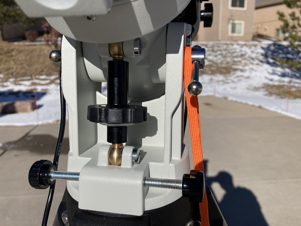
Figure 9. The improved azimuth and latitude alignment knobs on the iOptron CEM25P.
The latitude adjustment screw/knob provided on the iOptron was quite inadequate. (Refer to Figure 11.) The knurled part of the knob is only about 15/16" in diameter and the knurled/etched part of the knob were so shallow and smooth that one's finger and thumb could barely get enough grip on the knob to turn it. Add to that, you are trying to turn the knob while positioned at the rear of the RA Axis, peering through the Polar Align scope and the knob was next to impossible to easily turn with any positive control.
This problem was solved by adding a significantly larger knob, seen in Figure 9 - a knob with large tabs making the knob easy to grab with thumb and forefinger, and easy to located by feel alone. The larger diameter knob provides for much more torque on the latitude screw. The new knob is made from a knobbed screw/bolt of the type shown in Figure 10.

Figure 10. Knobbed Screw/Bolt.
Using a Dremel tool, I cut way the plastic around the bolt (Figure 10) and removed the bolt. Then I drilled a 15/16" hole in the middle of the knob and epoxied the knob to the existing latitude adjustment knob of the iOptron mount. The result is shown in Figures 11 and 12.
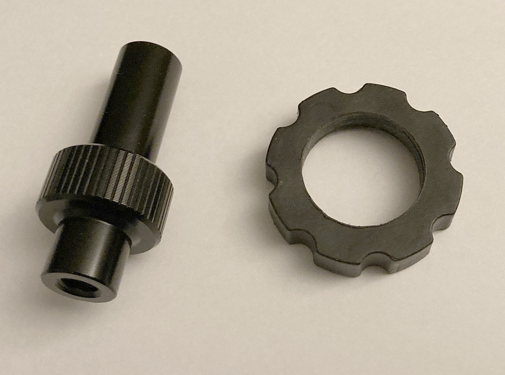
Figure 11. The stock Latitude Knob from iOptron (left), and the new "knob" (right) ready to install.

Figure 12. "New" Knob installed.
Refer back to Figure 9 to see how much nicer this larger knob is. And it works like a charm. Now, setting up the tripod and aligning it is easy. The tripod can be positioned, aligned to north, and leveled in no time and once Polaris becomes visible, looking through the Polar Scope, I can now reach forward and easily find the azimuth and latitude knobs and make the small changes needed to accurately align the RA Axis.
Positioning the tripod is now exceptionally easy:
- Roll the tripod out to the driveway
- Rotate the tripod (on its wheels) till the compass needle lines up
- Lower the jackscrews till the big bubble level is, well, "level"
- At dusk, as soon as Polaris is visible, make the quick fine adjustments to the latitude an azimuth of the mount
These four steps literally take only 5 minutes and Polaris is always in the FOV of the Polar Scope - sometimes already so close to the right spot only very minor adjustments need be made. Of course there are other setup tasks to perform to prepare for observing but at least this part is now no problem any more.
Bill Welker,
30 Dec, 2020
