Inexpensive Finderscope for Astronomy
When I set out to build a barn-door tracker a few months ago, I quickly realized that to set it up, relocate it, and set it up again in different locations on different nights, I'd need a way to quickly align it to the North Pole. I felt a simple sighting tube was too crude, yet a very nice "Telrad", (example: telescopes.com at $40 was somewhat "overkill".) (I had other projects in mind, meaning I'd be needing 3-4 finderscopes, so though a single Telrad would not break the bank, 4 of them would be unreasonably stressing on the budget!)
Somewhere along the way, while researching various designs of barn-door trackers, I came upon Rockett Crawford's article on ATMSITE.ORG, www.atmsite.org/contrib/Crawford/daisy/, (site now broken) and was intrigued. A quick check on Amazon.com showed these little Daisy gunsights, called the "Daisy Electronic Point Sight", could be purchased for $8.51 each, and needing four, the total came to $34.04 and free shipping! Four sights for the price of one Telrad! Not bad! Sure, the Daisy would not have the features of the Telrad, no red sighting rings (scaled to 1/2o, 2o, and 4o in diameter), but the little red dot projected in space seemed to be an adequate and elegant mechanism - just what I was looking for even though a simple tube would be quicker and cheaper.
Mr. Crawford in his article, provided details on modifying the Daisy sight to remove the reflective metallic coating on the sighting glass inside the plastic sight-ring - very nice - and demonstrated how he added a small potentiometer to the light's circuit to reduce the brightness of the built-in red LED. Hats off to Mr. Crawford and this article only serves to "add my $0.02", since I enjoyed modifying these Daisy sights! I thought I'd provide some additional tips should anyone want to do the same.
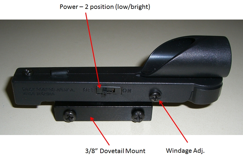
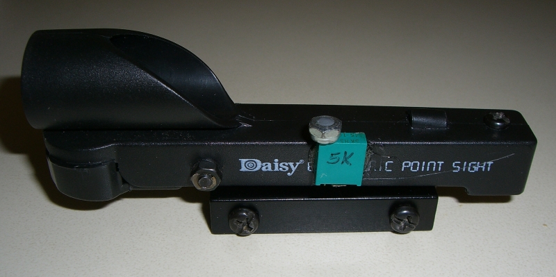
So here is the Daisy sight, left and right side views, with annotation of the parts:
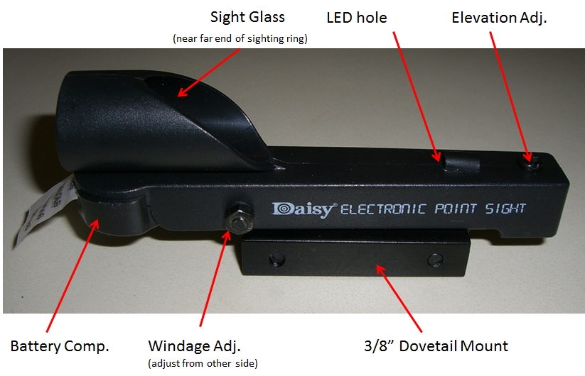
Obviously, the elevation and windage adjustments mean something entirely different when the sight is used as a finderscope. Nevertheless, after mounting the sight to a barn door tracker, or a telescope, the elevation and windage adjustments are nice for some fine adjustment when initially aligning the sight to the tracker or telescope. They definitely help if the alignment of the dove-tail mount to the tracker or scope was not quite "on-the-money".
For grins, these next two shots are simply views from the front and back of the sight. At left, is the front view, with the LED "on" so you can see its position and the aperture where it is located. At right, the rear view, illustrating the aerial image of the LED, reflected off the sight-glass.
The Daisy sight is not particularly durable. I'm not a gun hobbyist, but I can't imagine this thing lasting long in rough field use. But for re-purposing as a Finderscope, it is not bad at all! It takes a common CR2032 (3 volt) button battery, which can be replaced easily with a small Phillips screwdriver.
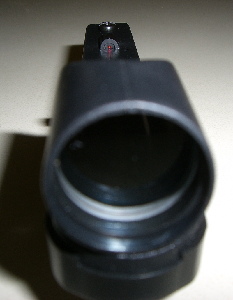
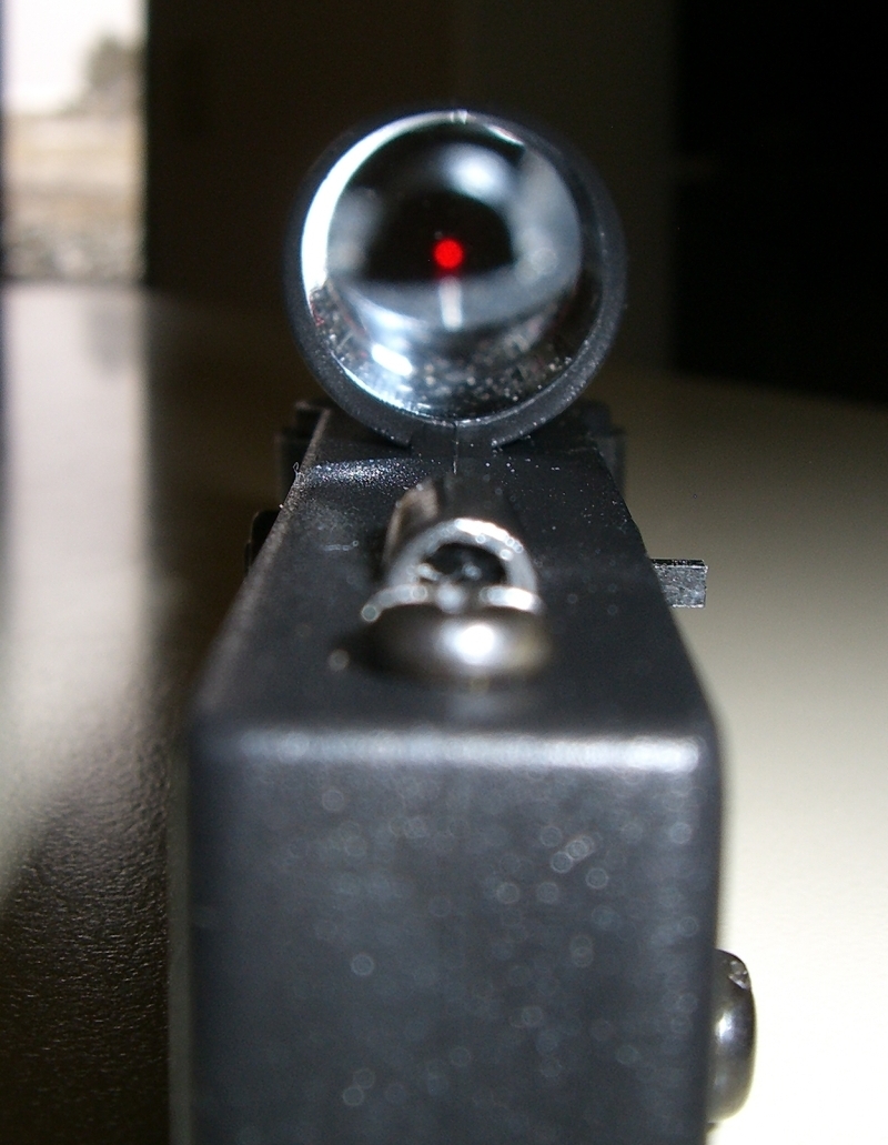
These views, above, are of the unmodified Daisy sight, so the LED reflection is quite bright, visible even in the daylight (as it was designed), and even still visible despite the camera's flash! For astronomical use, this brightness must be reduced and controlled, and that, of course, is the purpose of this project.
Removing the Reflective Coating
The Daisy sight was designed for outdoor use in the sun, and the reflective coating on the eye-side of the sight-glass is to ensure a bright enough reflection from the LED so the shooter can see the projected red-dot, yet still see through the glass to the target. Of course for astronomical use, the red dot projected from the glass with no coating is preferable, as we really don't want the stars - viewed through the glass - to be reduced in brightness by that coating on the glass! Mr. Crawford tells you how to remove the coating, and I only wish to add my experience as I had a bit of trouble. First, let's look at the visual effect of the coating to get an idea why we are doing this:

You can readily see from the image above, that when the coating is removed (left), it is a dramatic improvement over the neutral density of the coated sight glass (above, right)! So we really do want to remove that coating!
I'm no chemist, so this is "buyer beware" situation! You are on your own to study the safety requirements, and to take care not to hurt yourself or your household. This requires the use of "Muriatic Acid" - a weak but still dangerous form of hydrochloric (HCL) acid - and will cause harm to skin and metal. So wear rubber gloves, and do not do this over a metal sink or near metal appliances! An additional word of warning: Do this with plenty of ventilation! The chemical reaction of the hydrochloric acid with metal produces significant levels of hydrogen gas, which is not to be trifled with, and the gas carries with it the odor of metal salts which are also produced in the reaction, that is, it stinks. Also, once the reaction begins, hydrochloric acid vapor is released into the air due to the bubbling of the hydrogen gas being released, so surrounding metals are at risk of being affected by this vapor. Take care to do this work in an area which will be safe from these potential problems/dangers.
What you are trying to do is this: You want to initiate a chemical reaction between the muriatic acid, and the metal reflective coating on the sight-glass, so that the hydrochloric acid will react with the coating, turning it to a metal salt, thus removing it from the glass. The chemical reaction does not hurt the glass or the plastic frame of the Daisy sight. You will first, of course, want to disassemble as much as you can of the Daisy sight. Remove the battery, and the 3/8" dovetail mount and the elevation and windage screws, and remove the dovetail mount from the body. You want to control where the muriatic acid is applied, trying only to apply it to the silvered-side of the sight-glass. Fortunately, the acid will not harm the plastic body, so that will be OK. (Too bad the sight-glass is permanently installed in the plastic frame, as this whole process would be easier if the glass could first be removed from the sight!) The battery contacts should not be permitted to directly contact the muriatic acid or the vapors from the reaction, so do take care to avoid that.
I found that following Mr. Crawford's instructions using the metal spoon did not quite work! Perhaps it was the brand of muriatic acid I was using (less than 30%?), perhaps it was the spoon which was stainless steel, as I said, I am no chemist, but upon placing a few drops of the acid on the metal spoon, to initiate the reaction, nothing happened! But I soon discovered I could "trigger" the necessary reaction by placing some acid on aluminum foil and initiating the reaction with an old metal tent-stake (straight type tent-stake, about 3/16" diameter) I had in my shop. (A nail would probably have worked as well. What was apparently happening, is the tip of the tent-stake had enough oxidation on its surface, that it readily reacted with the acid, and once the chemical reaction began, the aluminum foil began to react as well).
So I modified Mr. Crawford's instructions thusly: With the Daisy sight held vertical, front pointing down, I placed a very small (about a 1/4" square) piece of aluminum foil on the sight glass. I put about a teaspoon of muriatic acid on the sight glass, enough to cover the glass, then I lightly touched the metal tent stake to the little piece of aluminum foil while ensuring the foil and tent-stake also touched the acid. The tip of the tent-stake reacted to the acid, the reaction continued in the aluminum foil, and in turn, the coating on the sight-glass. After a few seconds, in fact, when the small piece of foil was completely eaten away and the obvious chemical reaction had ceased, I flushed everything off the sight glass with water, then rinsed the end of the sight with vinegar, as Mr. Crawford suggested to remove any residue. After drying off any part of the sight that had gotten wet, I was most pleased to see that the metallic coating was completely gone, and holding the sight up to the daylight sky, I could see clearly through the sight-glass, as there was no coating to reduce the transmission of light through the glass! Success, and thank you Mr. Crawford!
(I should also now mention, that when I say "I flushed everything off with water", this was perfectly safe, though in reality, you are never supposed to mix water into acid, rather you are only supposed to mix acid into water! The old saying which I do remember from high school science is: "Poor old Joe lying calm and placid, for he poured water into acid!" When mixing water into acid, the mixing is highly exothermic and can, in some cases, release a lot of heat, resulting in the acid-water mixture exploding directly into your face. When you add instead acid into the water, the heat released is disipated in the water, and the possibility of an explosive release is avoided. But here, there was very little muriatic acid, which was already diluted (that's what muriatic acid is - diluted HCL acid), so there was no danger rinsing the device off with water.)
Adding the Trimpot (Trimmer Potentiometer)
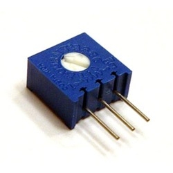
If you are not familiar with a "Trimpot", simply go to Google Images, and type "trimpot" in the search bar, and you will be presented with many images of the many and varied forms of these little potentiometers. There are basically two types, but one type is preferable, as I will attempt to explain.
Below, left, is the type Mr. Crawford used (apparently). This is the preferred type, because the small, white slotted circle in the middle is quickly rotated (with a small screwdriver) to set the desired resistance. A quick turn adjusts the brightness of the LED, and once the desired brightness is achieved, it really does not require adjusting again unless desired.
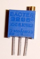
Above, right, is the second basic "type" of trimpot. Its adjustment is by the small brass knob on the top. This is the type if trimpot that is not desired because this design is for precise control of the resistance, and it takes many, many turns of the small brass knob to adjust the resistance. (Inside this version, is a screw which acts as a worm gear, and the resistor-wiper is attached to a multi-toothed spur gear. So for a rotation of the screw, the spur gear's rotation is greatly reduced in ratio, in the same manner as a worm gear, thus providing for precise control of the resistance.) This feature is not needed or desired in this project! But that does not mean this trimpot version can't be used! As you will see, this is the version I selected since I already had one on-hand. And you'll see how I handled the slow adjusting problem!
Modification of the circuit
It is a simple serial circuit being modified. The parts are small, room is tight, and as Mr. Crawford pointed out in his article, you must take care to not impact the volume inside the case where the dove-tail base is installed. You will be cutting a very small wire, and soldering in a tight space, so before you begin, take a moment to examine how much tolerance you have when the whole thing is reassembled. When you solder in the trimpot, the trimpot leads, and the wires must run very close to the inside edge of the plastic frame.
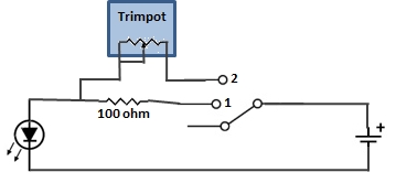
Below, left, is my crude drawing of the circuit as-designed, and to its right, the necessary modification to include the trimpot. I'm sure most reading this will scoff at the simplicity, and it is simple, but the difficulty, as I said, is in the small size of the parts, and the tight space to work in!
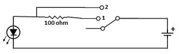
In this simple series circuit (left, above), it's obvious how it functions, but in case there is someone who'd like the explanation, I'll provide it. Looking at the left view, when the switch is in the "off" position (as shown), obviously the LED is not powered. When the switch is in position 1, the current flows through the 100 ohm resistor, and the LED illuminates. When the switch is moved to position 2, the resistor is bypassed, and current flows unrestricted to the LED - this is the "bright" setting.
So what we want to do is insert the trimpot in the circuit at switch position 2. (Retain stitch position 1 "as is" because you will want that "bright" setting. More on that in a moment.) In the modified circuit, you see the lead from switch position 2 has been cut and attached to the two ends of the trimpot. (This wire from switch position 2 may or may not be long enough to reach the leads of the trimpot. In my case it was, but I noticed in the 2nd Daisy sight I modified, this lead was too short and I had to add a short piece of my own wire. It is difficult to work in the confined space near the switch, but it is doable). The center lead from the trimpot (which provides the variable resistance), is simply connected to one of the two other leads on the trimpot (it does not matter which). With the trimpot installed, when the switch is in position 2, the current flows through the trimpot. How much current flows is determined by the trimpot's adjustment. Turned all the way to one side, the full resistance of the trimpot is used, and results in the dimmest LED. Turned all the way to the other side, the trimpot resistance is effectively removed, and the LED is once again at its brightest.
Mr. Crawford suggested a 10,000 ohm (10K ohm) trimpot, which is important because you will want the LED to be pretty dim!. But in my case, I used a 5K version, with leads on the bottom, simply because that's what I had, and tests showed it effectively dimmed the LED enough (though at night, in a very dark observing location, the dimmer light from a 10K trimpot would be really preferred.)
You want to keep switch position 1 because at least once, you may want to set up while the sky is still bright or you may want align the sight with your scope to some far distant object on the ground and you may be doing that when the sky is also bright. You will be glad you had the brighter position in those cases. Then, when the sky is dark, you will be very glad you inserted the trimpot for switch position 2 because the red light does need to be very dim when the sky is dark!
So here is my result! You see immediately how I solved the trimming problem - by simply epoxying a #2x56 locknut to the brass screw-end on the trimpot. I can rapidly turn the nut with my fingers while watching the LED brightness, till I am satisfied. The nut, making a tiny "knob" is actually a bonus, as it would be very awkward using a small screwdriver to turn the adjusting screw while watching the LED brightness change! (This is why other type trimpot is preferred.) Nevertheless, the #2 size nut fit easily over the adjusting screw head on the trimpot, and the epoxy I use is "JB Weld", which makes a rock-hard bond. (JB Weld can even be cut, sanded, and machined after it cures!) The "nut" is easily and quickly rotated with thumb and forefinger and accommodates for the fact that to change the LED brightness requires many turns! I marked an arrow on the side of the trimpot to indicate which way to turn the nut to increase the brightness.
Manufacture a dove-tail mount
Next, to mount the Daisy sight. To take advantage of the built-in 7/16" dove-tail mount on the sight, I decided to make a matching dove-tail base since I had 4 Daisy sights to mount. Starting with a piece of common aluminum stock, 3/4" wide by 1/8" thick, cut to 2" long, score one side of the surface at 7/16" and cut the pieces in two.
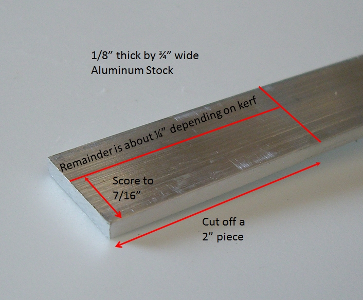
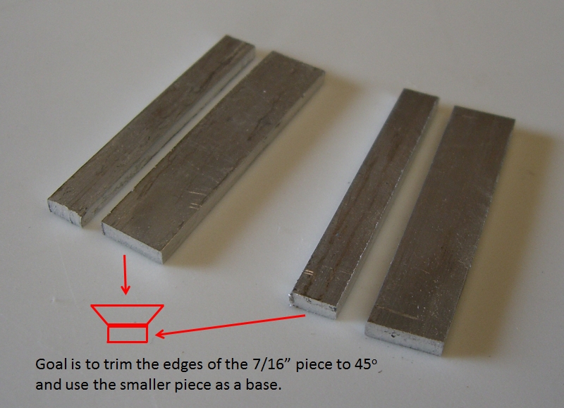
Cutting the piece in two results in a smaller piece, about 1/4" wide depending on the width of the cut. This remainder piece becomes the base. So in this next graphic, I've drawn in red, the shape we are looking for. The 7/16" piece needs its edges cut down by 45o, and then the 1/4" piece becomes the bottom.
Cutting 45o
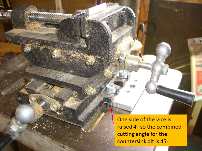
Trimming the edge of the 7/16" piece to 45o is no trivial task. It can be done with hand tools for a single production piece, but I needed to generate 4 of them, so I opted for a mechanical and reproducable way to do it. What I decided to to was "mill" the edge. I have several sizes of countersink bits, but all of them have an 82o face - half of which is 41o, so I needed a way to hold the 7/16" piece such that the additional 4o could be gained. What I decided on was this:
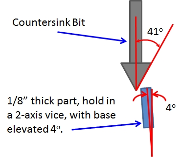
So here is my setup. The base of the vice is 5" across, so I raised the right side by 0.35", (5 x sin(4o)). Then, simply adjusting the two axes of the vice put the part in the right place, and then I cut the 45o chamfer by simply driving one side of the vice along the pre-positioned countersink bit - just like a mill lathe:
Here is a shot of a partial cut:
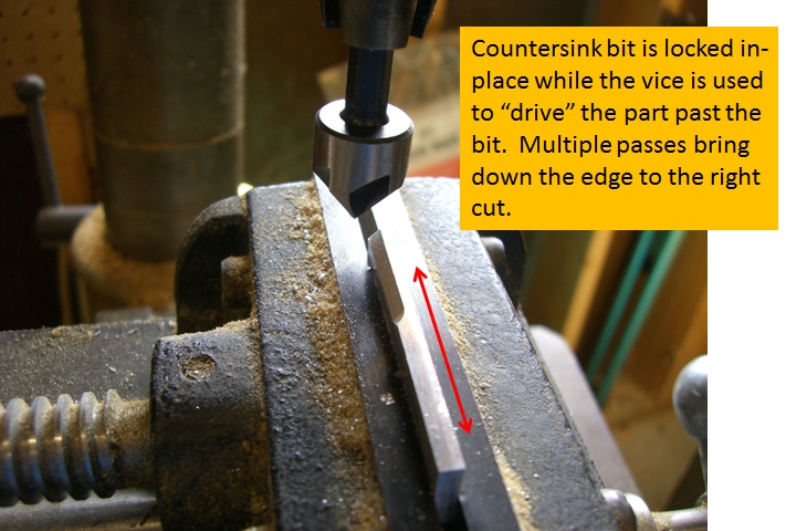
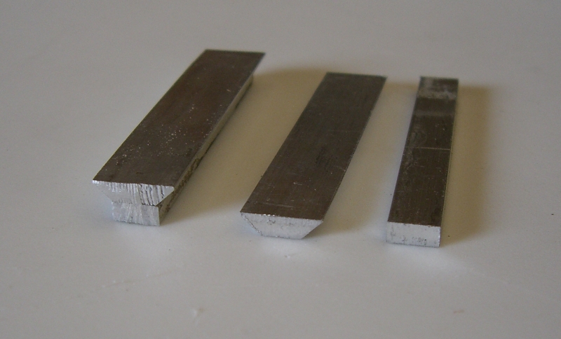
The precise position of the 1/8" part in the vice was not so important. Rather, clamping the part parallel in the vice jaws and the motion of the vice axis perpendicular to the axis of the countersink bit were important. So once I had the vice properly set up, all I needed to do was align the part in the vice jaw, using a machinist's rule so the edge was level. Here's a sample of the results before filing off the saw-cut marks. The assembled one, left, has simply been glued together with superglue. Since a flat-head machine screw will hold the entire assembly to a telescope tube, there is no other mechanical mating required between the two parts:
And finally, a test fit:
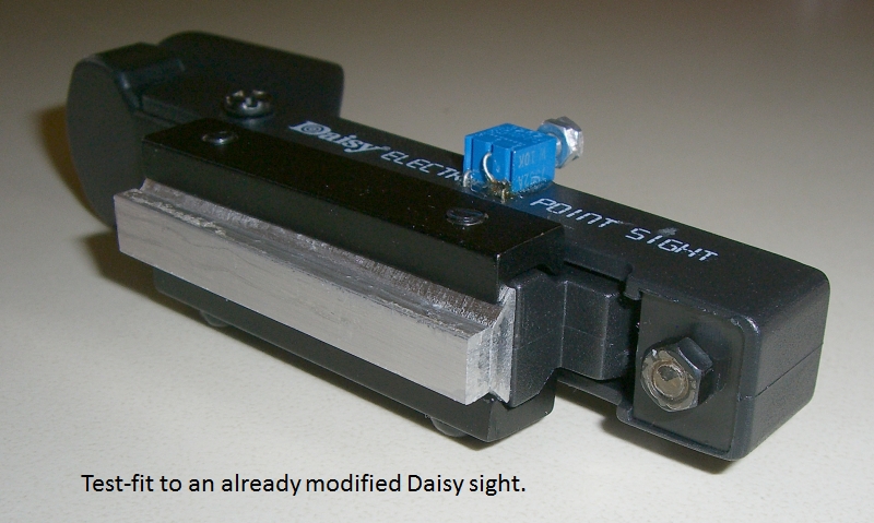
All that remains is to drill two holes in the dove-tail mount, and attach it to a 'scope or barn-door mount. The windage and elevation screws of the Daisy Sight allow for quick alignment of the sight to the optical axis of the scope. It's not a super-accurate finderscope, but it sure provides a quick and elegant way to point a scope to a desired location. Then, the regular, higher power optical scope, if so available, can be used for "finer" pointing. And for something like a barn-door mount, nothing but the Daisy Sight is needed, and it is terrific for that function!
I hope no one was troubled by my referencing Mr. Crawford's nice article on ATMSITE.org about the modification, and expanding on it a bit. The main thing I wanted to add were the steps I found necessary to initiate the chemical reaction with the muriatic acid. I felt this would be helpful to those attempting this project.
Bill Welker,
April, 2013
Last updated 20 May, 2014
